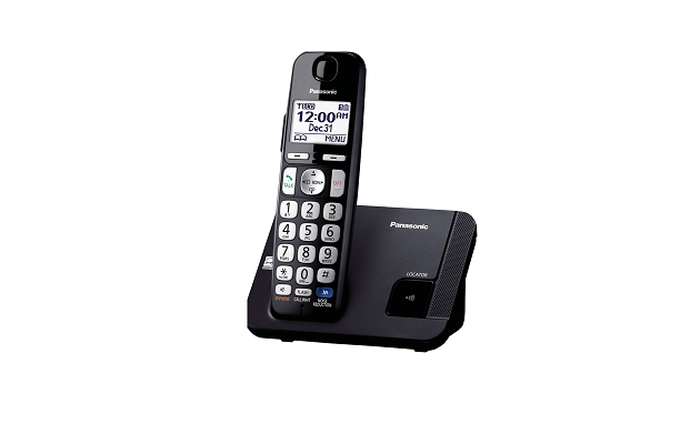
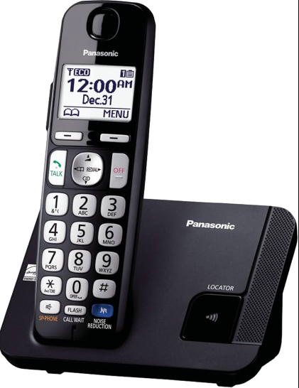
Panasonic KX-TGE210B Digital Cordless Phone
ORIGINAL SERVICE MANUAL INFORMATION
Please read these guides carefully before using the Panasonic KX-TGE210B Digital Cordless Phone User Manual.
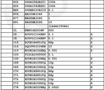
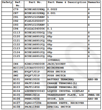
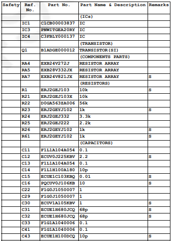
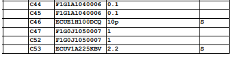
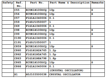
REPLACEMENT PARTS LIST
Please read these guides carefully before using the Panasonic KX-TGE210B Digital Cordless Phone User Manual.
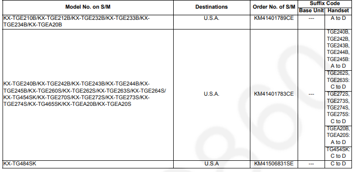
REFERENCE CHART
Note:
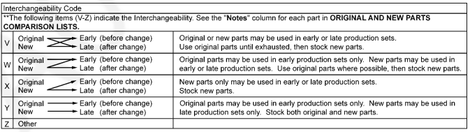
Alphabets in the “Remarks” column in the following lists correspond to the alphabets in the “Remarks” in REFERENCE CHART.
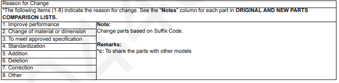
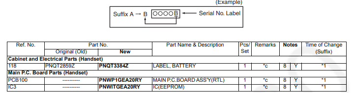
ORIGINAL AND NEW PARTS COMPARISON LISTS
Serial No. The label tells you the suffix code as follows.
- Please refer to “1 ORIGINAL SERVICE MANUAL INFORMATION”.
Note:
Please refer to “3.7. Schematic Diagram” (P.15), “3.8. Printed Circuit Board” (P.17), and “3.9. Replacement Parts List” (P.20) for details.
CHANGES (Suffix Code: D or later)
Please read these guides carefully before using the Panasonic KX-TGE210B Digital Cordless Phone User Manual.
Technical Descriptions
 Circuit Operation (Handset)
Outline
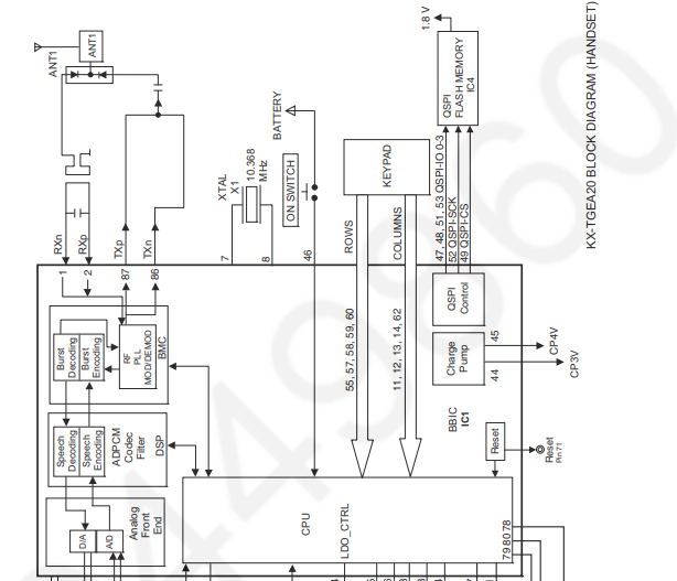
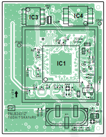
- Handset consists of the following ICs as shown in Block Diagram (Handset) (P.5).
- DECT BBIC (Base Band IC): IC1
- All data signals (forming/analyzing ACK or CMD signal)
- All interfaces (ex: Key, Detector Circuit, Charge, DC/DC Converter, EEPROM, LCD, RF Power Amp.)
- PLL Oscillator
- Detector
- Compress/Expander
- Reception
- Integrated 1.9 GHz PA for DECT
- QSPI FLASH MEMORY: IC4
- Main Program D/L Area
- EEPROM: IC3 Following information data is stored – Settings ex: ID code, user setting
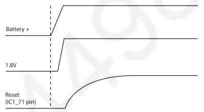
Power Supply Circuit/Reset Circuit
Circuit Operation:
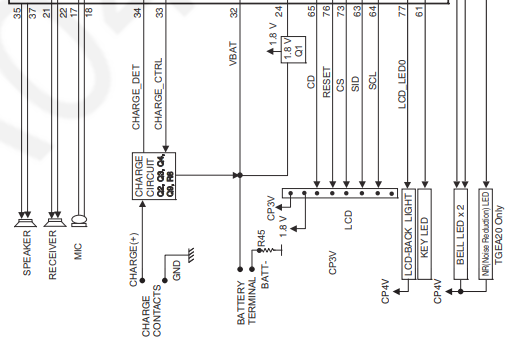
When power on the Handset, the voltage is as follows; BATTERY(2.2 V ~ 2.6 V: BATT+) -> Q1 (1.8 V), IC1-44pin (CP3V) The Reset signal generates IC1 (71 pin) and 1.8 V.
Charge Circuit
When charging the handset on the Base Unit, the charge current is as follows;
DC+(5.5 V) -> R371 -> R372 -> D362 -> CHARGE+(Base) -> CHARGE+(Handset) -> -> Q3 -> BATTERY+… Battery…
BATTERY- -> R45 -> GND -> CHARGE-(Handset) -> CHARGE-(Base) -> GND -> DC-(GND)
In this way, the BBIC on Handset detects the fact that the battery is charged. The charge current is controlled by switching the Q9 of the Handset. Refer to Power Supply Circuit/Reset Circuit.
Battery Low/Power Down Detector
- “Battery Low” and “Power Down” are detected by BBIC which checks the voltage from the battery. The detected voltage is as follows;
- Battery Low Battery voltage: V(Batt) 2.25 V ± 50 mV The BBIC detects this level and ” ” starts flashing.
- Power Down Battery voltage: V(Batt) 2.0 V ± 50 mV The BBIC detects this level and power down.
Speakerphone
The hands-free loudspeaker at SP+ and SP- is used to generate the ring alarm.
Handset
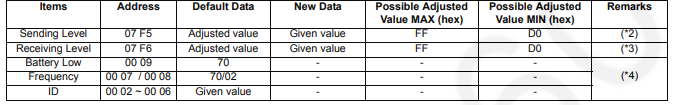
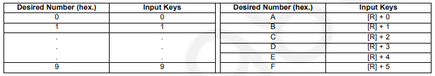
Note:
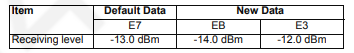
When you enter the address or New Data, please refer to the table below.
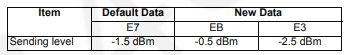
 When adding “01” (hex) to the default value, the sending level increases by 0.25 dB. ex.)
 When reducing “01” (hex) from the default value, the receiving level increases by 0.25 dB. ex.)
 Use these items in a READ-ONLY mode to confirm the contents. Careless rewriting may cause serious damage to the handset.
Troubleshooting Guide
Check Power
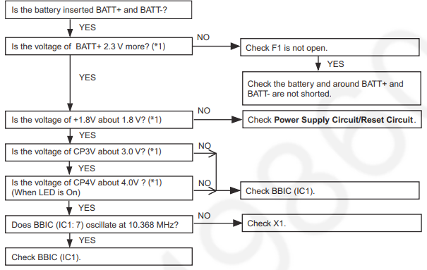
Cross Reference:
Power Supply Circuit/Reset Circuit (P.6)
Note:
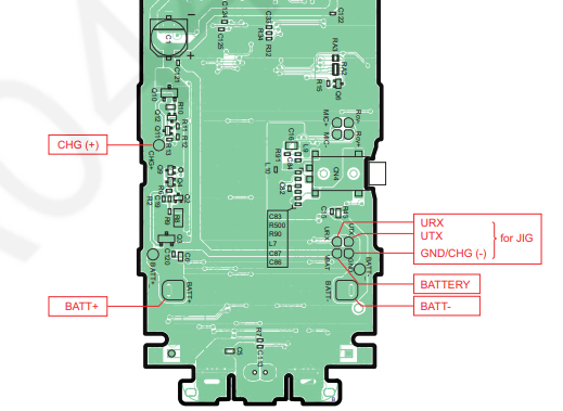
- Refer to Circuit Board (Handset_Main) (P.17).
Check Link
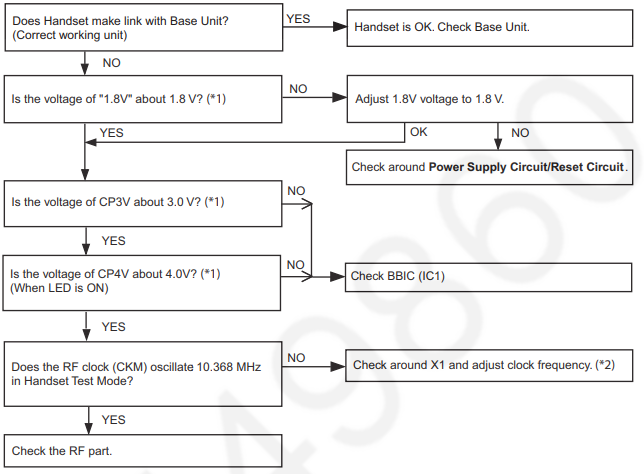
Cross Reference:
Power Supply Circuit/Reset Circuit (P.6)
Check the RF part (P.10)
Note:
- Refer to Circuit Board (Handset_Main) (P.17).
- Refer to Check Point (Handset) (H)
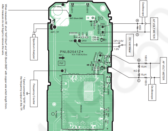
Check the RF part
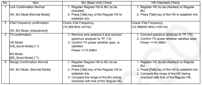
Note:
- Refer to Commands.
- Adjustment Standard (Base Unit).
- Adjustment Standard (Handset) (P.12)
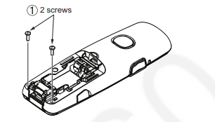
Disassembly and Assembly Instructions
- Remove the 2 screws.
 Insert a plastic card. (Ex. Used SIM card etc.) between the cabinet body and the cabinet cover, then pull it along the gap to open the cabinet.
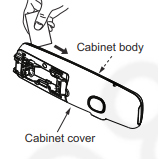
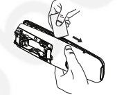 Likewise, open the other side of the cabinet.
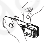 Remove the cabinet cover by pushing it upward.
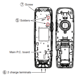
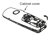 Remove the solders.
- Remove the solders to remove the 2 charge terminals.
- Remove the screw to remove the main P. C. board.
Measurements and Adjustments
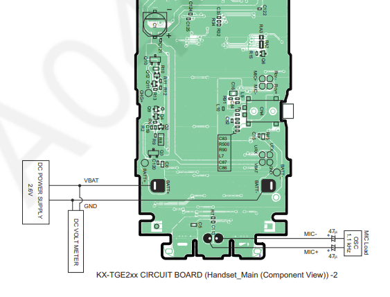
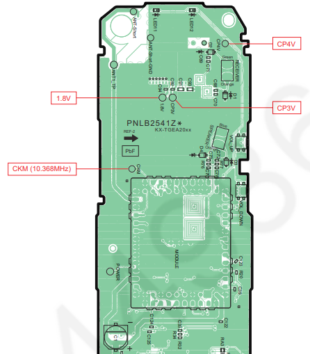
Component View
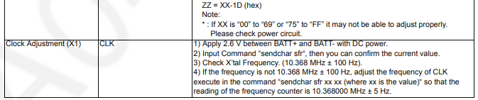
Things to Do after Replacing X’tal
First, operate the PC setting according to The Setting Method of JIG. Then download the appropriate data according to the following procedures.
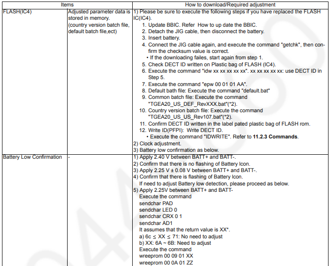
Note:
- WW: country code, XXX_YYY: revision number WW: country code, XXX: revision number “XXX_YYY” vary depending on the country version.
- “XXX” vary depending on the country version. You can find them in the batch file, PNZZ- mentioned in The Setting Method of JIG.
Miscellaneous
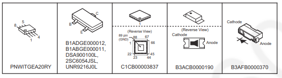
Terminal Guide of the ICs, Transistors and Diodes
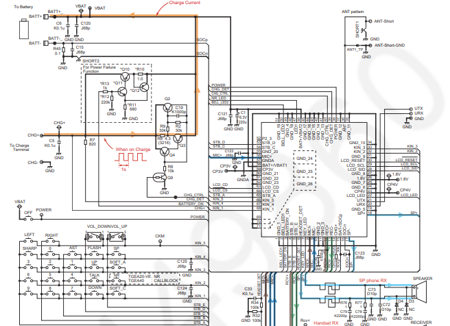
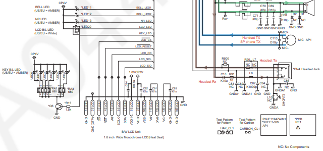
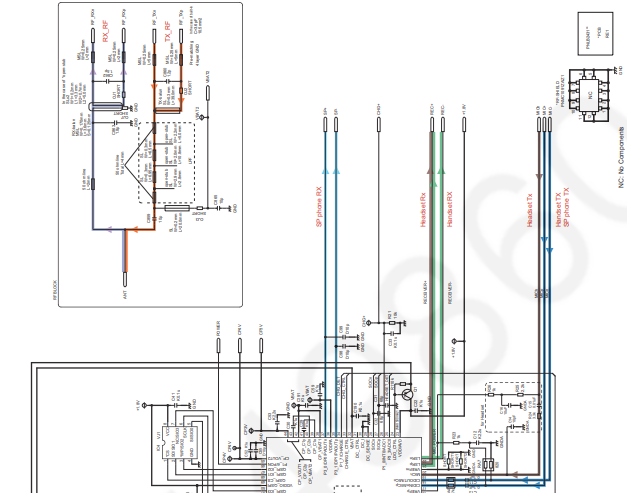
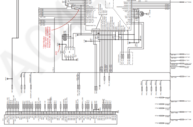
Schematic Diagram
Schematic Diagram (Handset_Main)
Schematic Diagram (Handset_Module)
Printed Circuit Board
Please read these guides carefully before using the Panasonic KX-TGE210B Digital Cordless Phone User Manual.
Component View
Bottom View

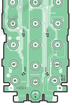
Circuit Board (Handset_Module)
Component View
Bottom View

Replacement Parts List
Handset
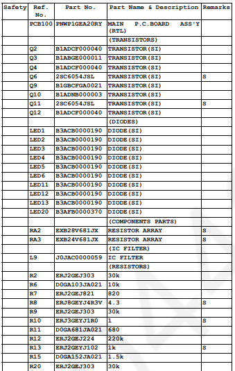
Module P.C.Board
Contact Information
Website: https://na.panasonic.com/us/
Download Pdf