Panasonic FV-SW20VEC1 Intelli Balance
GENERAL SAFETY INFORMATION
For Your Safety
- The following symbols are used to classify and describe the type of instructions to be observed.
- “‘- This symbol is used to alert users to a specific operating procedure that must not be performed.
- This symbol is used to alert users to a specific operating procedure that must be V followed to operate the unit safely. This symbol is used to alert users not to disassemble the equipment.
- Do not install using methods not approved in the instructions.
- Disconnect the power source before working on the product.
- Do not disassemble the unit. It may cause fire or electric shock.
- Never install the unit in a high-humidity space.
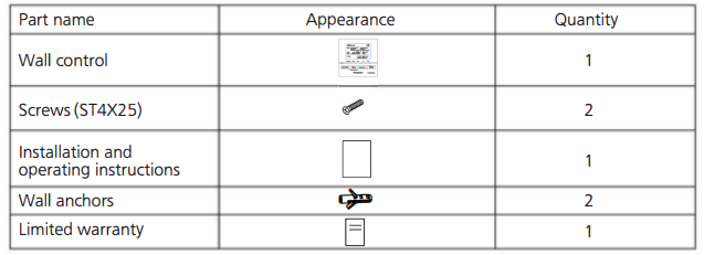
SUPPLIED ACCESSORIES
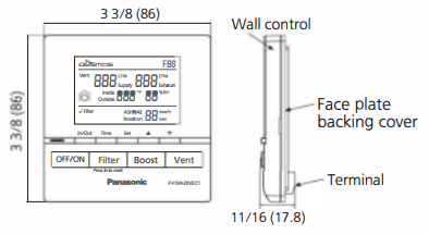
DIMENSIONS
INSTALLATION
- wiring preparation
- It’s recommended to use the cable (14AWG~26AWG) for connecting the product and V wall control, and the length should not be longer than 33.3 ft (10 m).
Note)
Strip insulation cover for each wire as shown below. Unit: inches (mm)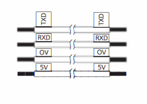
INSTALLATION
2. installing the wall control
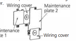
- Open the knock-out hole and remove maintenance plates 1 and 2 and the wiring
- Thread cables through conduits respectively and install the conduits into knock-out holes.
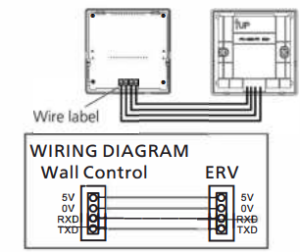
- Insert cables into the corresponding terminals of the product. Make sure the lead wire labels correspond to the terminal label and the screw of the terminal securely fastens the copper wire and no copper wire is exposed
- Re-install the wiring covers and maintenance plates.
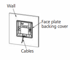
- Remove the face plate backing cover from the backing plate with a small flat screwdriver
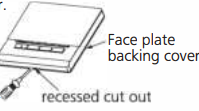
- Temporarily put the face plate backing cover on the wall, mark the terminal hole and screw positions
- Remove the face plate backing cover, cut the terminal hole, and drill screw holes (<D5/32 ft (<D4 mm)).
- Insert wall anchors, and fix the face plate backing cover on the wall with two screws
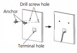
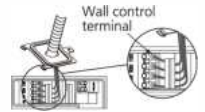
- Route the cables from the unit to the terminal hole.
- Insert cables into the corresponding terminals of wall control according to the lead wire labels.
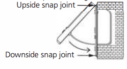
- Fix the wall control screen to the face plate backing cover. Upside snap joint
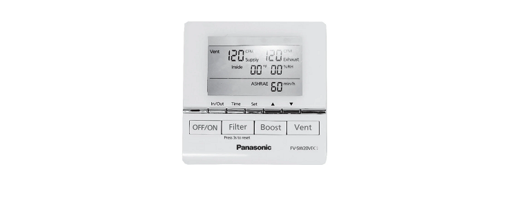
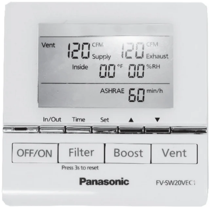
BUTTON AND DISPLAY DESCRIPTION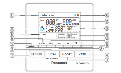
- OFF/ON Button Product standby/ running
- Filter Reset Button Press the button after maintenance to reset accumulated running time
- Boost Button Activate / Deactivate Boost Mode
- Vent Button Set supply air volume/exhaust air volume
- Boost display Light Green: Boost mode on
- In/Out Button Display the inside or outside temperature and humidity
- Time Button
• Set Boost time
• Set ASHRAE time - Set Button Confirm the air volume/time setting
- Button
• Set the air volume setting
•Set time “min, min/h” - Filter Maintenance Display The Display filter needs to be cleaned or changed
- ASHRAE/Boost on time Display
•Display ASHRAE time
•Display Boost time - Display Defrost Mode Display the product in low-temperature protection mode
• Air exchange:
• Circulation: ID• Stop operating: - Display inside & outside temperature and humidity
•Display inside temperature and humidity
• Display outside temperature and humidity - Air volume Display Display supply air volume and exhaust air volume
OPERATION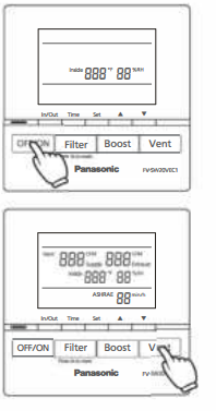
- Standby mode
- Set Button Confirm the air volume/time setting
- ASHRAE/Boost on time Display
•Display ASHRAE time
•Display Boost time - Air volume Display Display supply air volume and exhaust air volume
- COSMOS Display Display when Cosmos
- module is connected
•Press ” I oFF/oN I”, and the unit starts/standby
•The inside temperature ( and humidity(%) display in standby mode
•The unit operates in the last mode before stopping
(Note)
When connected to the wall control, the control panel of the FV-20VEC1 will be disabled. When the wall control is disconnected from the ERV,
the ERV controls will be enabled. Function mode
air volume setting (Default: 120 CFM) G) Press” I vent I” to switch between supply air volume and exhaust air volume
- Press”c=:::J” to choose and press”_. T” to adjust the volume (60, 80, 100, 120, 140, 160, 180, 200). ® Press “c::==J” again to confirm the setting
OPERATION$
ASHRAE time setting (Default: 60 min/h) Time CD Press the” C=::J” to change the ASH RAE time. Set Vent BBB” Supply BBB” Exhaust I]) Press “e=::J” to choose and press “.._ T” to adjust the,;, 888” 88%'” ASH RAE time (60, 50, 40, 30, 20, 10). ASHRAE 8B min/h Set ® Press”e=::J” again to confirm the setting.
Note
- For more detailed information regarding the ASHRAE intermittent timer control, please refer to the FV-20VEC1 manual. In/Out
- Press “C=::J” to switch temperature and humidity between inside and outside.
- Defrost mode FV–5W20VEC1
- When the outdoor temperature<14 °F, ERV will enter defrost mode, defrost icon will be displayed as below. CD Heat exchange: Defrost icon display
Circulation:
- Stop operating: Defrost icon display
About defrost mode
- The max ventilation air volume setting is 180 CFM in defrost mode.
- When the ventilation air volume is 60 CFM~120 CFM, the circulation air volume is 180 CFM. When ventilation air volume is 130 CFM ~ 180 CFM, circulation air volume is 230 CFM.
- For more detailed information regarding the defrost mode, please refer to the FV-20VEC1 manual
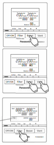
Boost mode
- Press II I Boost I II to enter boost mode, supply and exhaust air volume constant to 200 CFM.
- Boost on _time setting (Default: 20 min) Time
- CD Press 11c=:J11 to change the boost on time, and press 11 _. T to adjust (60, 50, 40, 30, 20, 10)
- Press 11c::::=J” to confirm the setting
- Exit boost mode: CD Timer finishes.
- Press II I Boost I II again.
- Press II I vent I ” to set supply and exhaust air volume, and then ERV will exit boost mode.
Note)
- Boost air volume will be constant at 180 CFM when outdoor temperature<14 °F.
- For more detailed information on “Boost features and functions” please refer to the FV-20VEC1 manual.
Filter reset
- When the filter requires cleaning, 11 ✓ Filter II will display.
- Press II I Filter I 11 for 3 seconds to cancel the 11 ✓ Filter II display after filter maintenance.
TROUBLESHOOTING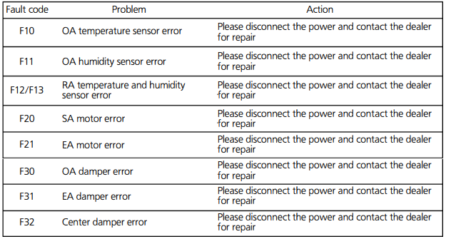
SPECIFICATIONS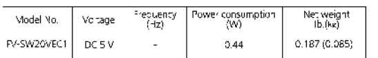
PRODUCT SERVICE
- Warning Concerning Removal of Covers.
- Should your unit require service or parts, call the Panasonic Call Center at 1-866-292-7299 (USA)
- or 1-800-669-5165 (Canada).
- Panasonic Corporation of North America
- Two Riverfront Plaza, Newark, NJ 07102
- www.panason1c.com
- Panasonic Canada Inc.
- 5770 Ambler Drive, Mississauga, Ontario L4W 2T3
- www.panason1c.com
- © Panasonic Corporation 202